Assembly instructions
PK1 Extreme Stand Aluminum / Aluminium Base ( ALU BASE )
It is a requirement to remove all of your AV components from your PK1 Extreme Stand for this assembly process. Treat it as though the stand is new.
Step : Flip your PK1 Stand over and remove the rubber feet and lower struts. The rubber feet may be used for additional support in the last step of this guide if the adhesive is still good
Step : Loosely connect the Left and Right rear L-Brackets to the lower holes of each of the sides of your PK1 Extreme Stand. We will tighten later once connected and aligned to the ALU BASE
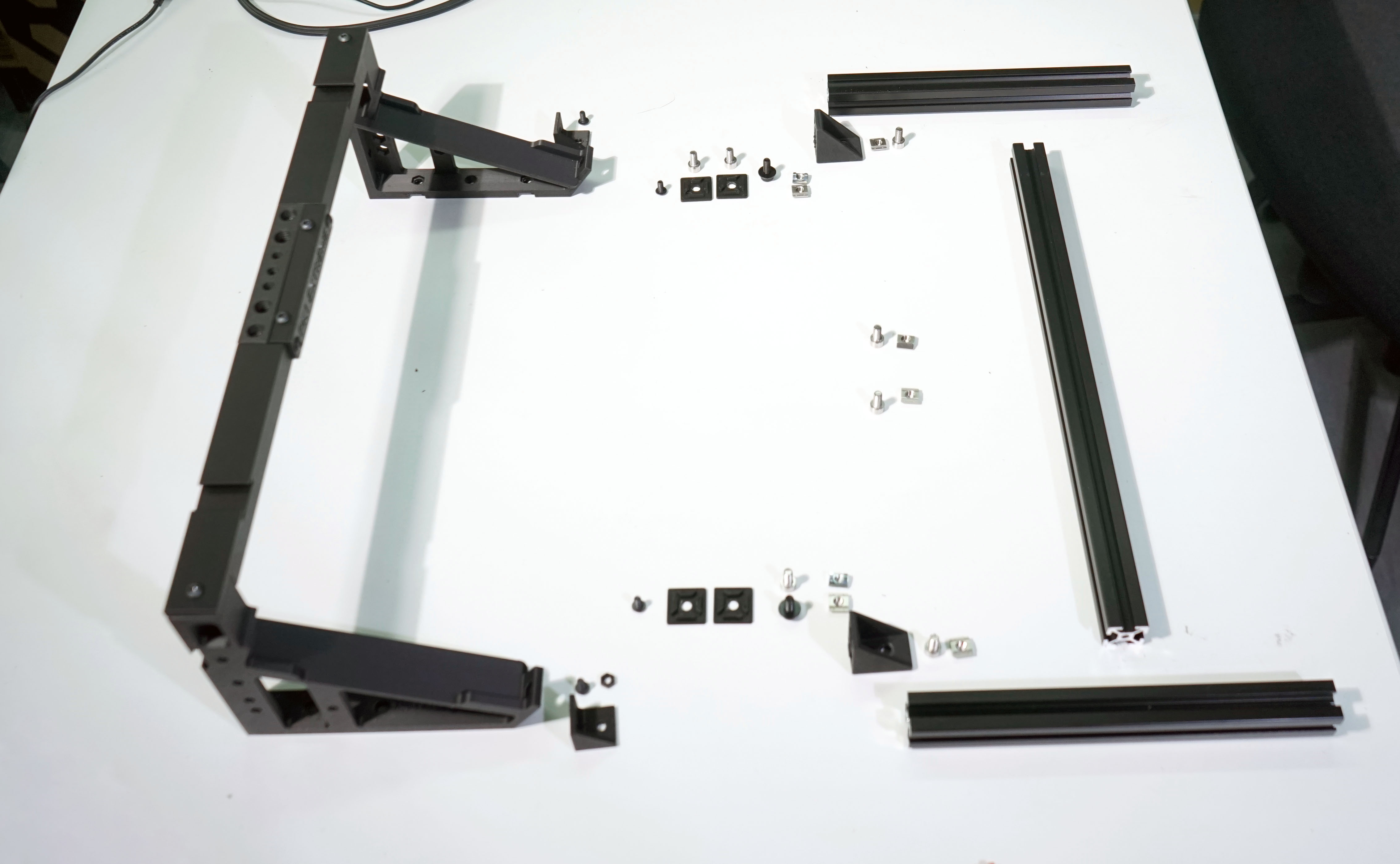
Step : Lay out the supplied 1:1 Scale diagram of the ALU BASE on a large flat surface so that the text is upright an facing you.
Step : Place each of the extrusion bars in their corresponding positions over the diagram so you get a feel for the construction. There is no up or down on the extrusions
Step : Lift up the middle extrusion and slide in an M5 T-Nut into the extrusion channel from the left hand side. The channel you chose is now the FRONT.
Step : Following the orientation of the diagram, loosely attach the single hole side of a corner bracket to the T-Nut you inserted into the extrusion from the left with an M5x10 bolt
Step : Slide the corner bracket so that the left edges are lined up exactly. Tighten slightly to hold the left hand corner bracket in place
Step : Insert another M5 T-Nut from the Right hand side of the middle extrusion in the same channel as before ( the front ) and loosely attach the corner bracket using the single hole side facing the T-Nut
Step : Slide the corner bracket so that the right edges are lined up exactly. Tighten slightly to hold the right hand corner bracket in place
Step : Pick up the Left hand extrusion and insert an M5 T-Nut into one of the channels. This is now the INSIDE
Step : Loosely attach an M5x10 bolt from the left corner bracket to the left inside T-NUT so the Left extrusion can slide along the T-Nut from front to back for alignment purposes
Step : Using the provided plastic jig, hold it flat against the INSIDE LEFT extrusion with the front of the jig lining up with with the front of the left extrusion. Slide the LEFT EXTRUSION so that the left corner bracket hits the plastic jig you're holding in place. Slightly tighten the left M5 corner bracket bolt to the left extrusion T-Nut
Step : Pick up the Right hand extrusion and insert an M5 T-Nut into one of the channels. This is now the INSIDE
Step : Loosely attach an M5x10 bolt from the right corner bracket to the right inside T-NUT so the Right extrusion can slide along the T-Nut from front to back for alignment purposes
Step : Using the provided plastic jig, hold it flat against the INSIDE RIGHT extrusion with the front of the jig lining up with with the front of the right extrusion. Slide the RIGHT EXTRUSION so that the left corner bracket hits the plastic jig you're holding in place. Slightly tighten the right M5 corner bracket bolt to the right extrusion T-Nut
Step : Using the plastic jig as a guide, verify that the distances between the fronts of the left and right extrusions are the same to the front edge of their respective corner nuts
Step : Once all distances are confirmed, tighten the M5 bolts holding the corner nuts in place
Step : Lay the extrusion frame down such that the corner brackets are facing the front
Step : We are about to use 2 different type of T-Nuts into the TOP channel of the Left and Right extrusions. The front T-Nut is an M5 while the rear T-Nut is an M4
Step : Slide an M5 T-Nut into the Left FRONT Top channel and place it about the length of the plastic jig from the front
Step : Slide an M4 T-Nut into the Left REAR Top channel and place it about half way between the back edge of the Left extrusion and the middle extrusion
Step : Slide an M5 T-Nut into the Right FRONT Top channel and place it about the length of the plastic jig from the front
Step : Slide an M4 T-Nut into the Right REAR Top channel and place it about half way between the back edge of the Right extrusion and the middle extrusion
Step : Place your PK1 Extreme Stand over the ALU BASE, positioning the rear L-Brackets over the Top Rear M4 T-Nuts
Step : Loosely tighten an M4 bolt into each of the Rear M4 T-Nuts but not too tight that you cannot slide the PK1 Stand back and forth
Step : Slide the PK1 Stand back and forth so you can insert and loosely tighten an M5x16 Bolt through the lower centre hole of each PK1 Stand side into the previously inserted Front M5 T-Nuts on the Left and Right sides
Step : Now slide the entire PK1 Stand back and forth on the ALU BASE until the notch under the PK1 side from the removed rear strut lines up with the centre of the middle extrusion
Step : Repeat this step for both Left and Right sides. Once in position, tighten the M5x16 Bolt. Do not over tighten
Step : Now adjust the position of the rear L-Brackets and tighten first to the rear of each PK1 Stand side THEN the to the top channel
Step: Place and endcap over each end of the exposed extrusion and tighten using an M5x6 bolt. This is purely cosmetic and does not need to be overly tight
Step : Place the supplied rubber feet in the marked positions on the diagram, and if you retained your original rubber feet, feel free to add those along the ALU BASE underside as well
Step : You should now have a rigid frame set up